_%E7%88%B1%E7%BB%99%E7%BD%91_aigei_com.gif)


stm32时钟系统分析
stm32时钟系统分析
时钟介绍:简单来说,时钟是具有周期性的脉冲信号,最常用的是占空比50%的方波
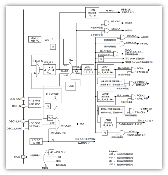
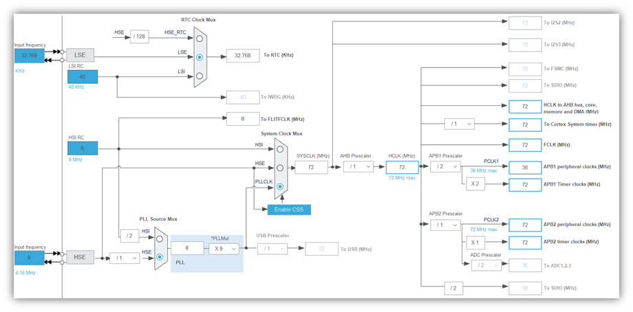
系统时钟是如何产生的?
硬件分析:

H:high
L:low
S:speed
I:internal
E:external
代码分析:
在system_stm103f10x.c中有void SystemInit (void) 函数,该函数内容如下:
void SystemInit (void)
{
  RCC->CR |= (uint32_t)0x00000001;
  /*该行代码会将CR寄存器的第0位(因为寄存器的位是从0开始的)置1
  RCC->CR寄存器分析:
          在中文手册查阅此寄存器的第0位有如下说明--0:内部8MHz振荡器关闭;内部8MHz振荡器开启。
          可知上述代码开启了8MHZ的晶振,即HSI(高速内部振荡器)。
  */
//SystemInit()函数有许多的条件编译我们主要来看看SetSysClock()这个函数。
#ifndef STM32F10X_CL
  RCC->CFGR &= (uint32_t)0xF8FF0000;

#else
  RCC->CFGR &= (uint32_t)0xF0FF0000;
#endif /* STM32F10X_CL */

  /* Reset HSEON, CSSON and PLLON bits */
  RCC->CR &= (uint32_t)0xFEF6FFFF;

  /* Reset HSEBYP bit */
  RCC->CR &= (uint32_t)0xFFFBFFFF;

  /* Reset PLLSRC, PLLXTPRE, PLLMUL and USBPRE/OTGFSPRE bits */
  RCC->CFGR &= (uint32_t)0xFF80FFFF;

#ifdef STM32F10X_CL
  /* Reset PLL2ON and PLL3ON bits */
  RCC->CR &= (uint32_t)0xEBFFFFFF;

  /* Disable all interrupts and clear pending bits  */
  RCC->CIR = 0x00FF0000;

  /* Reset CFGR2 register */
  RCC->CFGR2 = 0x00000000;
#elif defined (STM32F10X_LD_VL) || defined (STM32F10X_MD_VL) || (defined STM32F10X_HD_VL)
  /* Disable all interrupts and clear pending bits  */
  RCC->CIR = 0x009F0000;

  /* Reset CFGR2 register */
  RCC->CFGR2 = 0x00000000;
#else
  /* Disable all interrupts and clear pending bits  */
  RCC->CIR = 0x009F0000;
#endif /* STM32F10X_CL */

#if defined (STM32F10X_HD) || (defined STM32F10X_XL) || (defined STM32F10X_HD_VL)
  #ifdef DATA_IN_ExtSRAM
    SystemInit_ExtMemCtl();
  #endif /* DATA_IN_ExtSRAM */
#endif

  /* Configure the System clock frequency, HCLK, PCLK2 and PCLK1 prescalers */
  /* Configure the Flash Latency cycles and enable prefetch buffer */
  **SetSysClock();**

#ifdef VECT_TAB_SRAM
  SCB->VTOR = SRAM_BASE | VECT_TAB_OFFSET; /* Vector Table Relocation in Internal SRAM. */
#else
  SCB->VTOR = FLASH_BASE | VECT_TAB_OFFSET; /* Vector Table Relocation in Internal FLASH. */
#endif
}
上述代码可知SystemInit函数会调用SetSysClock()函数,该函数原型如下:
static void SetSysClock(void)
{
//该函数通过宏来判断系统定义的是多高频率的宏来调用对应的函数设置系统时钟的
#ifdef SYSCLK_FREQ_HSE
  SetSysClockToHSE();
#elif defined SYSCLK_FREQ_24MHz
  SetSysClockTo24();
#elif defined SYSCLK_FREQ_36MHz
  SetSysClockTo36();
#elif defined SYSCLK_FREQ_48MHz
  SetSysClockTo48();
#elif defined SYSCLK_FREQ_56MHz
  SetSysClockTo56();
**#elif defined SYSCLK_FREQ_72MHz**
  **SetSysClockTo72();**
#endif

 /* If none of the define above is enabled, the HSI is used as System clock
    source (default after reset) */
}
在system_stm103f10x.c的115行有:
**#define SYSCLK_FREQ_72MHz 72000000**
可知系统默认定义的是72M,此时会调用SetSysClockTo72()函数,该函数原型如下:
static void SetSysClockTo72(void)
{
    //__IO解释:#define     __IO    volatile
  __IO uint32_t StartUpCounter = 0, HSEStatus = 0;
  //RCC_CR_HSEON解释:#define  RCC_CR_HSEON      ((uint32_t)0x00010000)
  //0: HSE振荡器关闭;1: HSE振荡器开启。
  RCC->CR |= ((uint32_t)RCC_CR_HSEON);//使能HSE

  //等待外部高速时钟就绪标志置位(时钟初始化需要等待其稳定)
  do
  {
      //RCC_CR_HSERDY:#define  RCC_CR_HSERDY                   ((uint32_t)0x00020000)
      //位17--0:外部4-16MHz振荡器没有就绪;1:外部4-16MHz振荡器就绪。
    HSEStatus = RCC->CR & RCC_CR_HSERDY;
    StartUpCounter++;
  } while((HSEStatus == 0) && (StartUpCounter != HSE_STARTUP_TIMEOUT));

  if ((RCC->CR & RCC_CR_HSERDY) != RESET)////判断时钟是否就绪并设置标志变量
  {
    HSEStatus = (uint32_t)0x01;
  }
  else
  {
    HSEStatus = (uint32_t)0x00;
  }

  if (HSEStatus == (uint32_t)0x01)////HSE时钟已经准备就绪
  {
    //使能FLASH相关寄存器
    //#define  FLASH_ACR_PRFTBE                 ((uint8_t)0x10)
    FLASH->ACR |= FLASH_ACR_PRFTBE;

    /* Flash 2 wait state */
    FLASH->ACR &= (uint32_t)((uint32_t)~FLASH_ACR_LATENCY);
    FLASH->ACR |= (uint32_t)FLASH_ACR_LATENCY_2;


    /* HCLK = SYSCLK */
    RCC->CFGR |= (uint32_t)RCC_CFGR_HPRE_DIV1;

    /* PCLK2 = HCLK */
    RCC->CFGR |= (uint32_t)RCC_CFGR_PPRE2_DIV1;

    /* PCLK1 = HCLK */
    RCC->CFGR |= (uint32_t)RCC_CFGR_PPRE1_DIV2;

#ifdef STM32F10X_CL
    /* Configure PLLs ------------------------------------------------------*/
    /* PLL2 configuration: PLL2CLK = (HSE / 5) * 8 = 40 MHz */
    /* PREDIV1 configuration: PREDIV1CLK = PLL2 / 5 = 8 MHz */

    RCC->CFGR2 &= (uint32_t)~(RCC_CFGR2_PREDIV2 | RCC_CFGR2_PLL2MUL |
                              RCC_CFGR2_PREDIV1 | RCC_CFGR2_PREDIV1SRC);
    RCC->CFGR2 |= (uint32_t)(RCC_CFGR2_PREDIV2_DIV5 | RCC_CFGR2_PLL2MUL8 |
                             RCC_CFGR2_PREDIV1SRC_PLL2 | RCC_CFGR2_PREDIV1_DIV5);

    /* Enable PLL2 */
    RCC->CR |= RCC_CR_PLL2ON;
    /* Wait till PLL2 is ready */
    while((RCC->CR & RCC_CR_PLL2RDY) == 0)
    {
    }


    /* PLL configuration: PLLCLK = PREDIV1 * 9 = 72 MHz */
    RCC->CFGR &= (uint32_t)~(RCC_CFGR_PLLXTPRE | RCC_CFGR_PLLSRC | RCC_CFGR_PLLMULL);
    RCC->CFGR |= (uint32_t)(RCC_CFGR_PLLXTPRE_PREDIV1 | RCC_CFGR_PLLSRC_PREDIV1 |
                            RCC_CFGR_PLLMULL9);
#else
    /*  PLL configuration: PLLCLK = HSE * 9 = 72 MHz */
    RCC->CFGR &= (uint32_t)((uint32_t)~(RCC_CFGR_PLLSRC | RCC_CFGR_PLLXTPRE |
                                        RCC_CFGR_PLLMULL));
    RCC->CFGR |= (uint32_t)(RCC_CFGR_PLLSRC_HSE | RCC_CFGR_PLLMULL9);
#endif /* STM32F10X_CL */

    /* Enable PLL */
    RCC->CR |= RCC_CR_PLLON;

    /* Wait till PLL is ready */
    while((RCC->CR & RCC_CR_PLLRDY) == 0)
    {
    }

    /* Select PLL as system clock source */
    RCC->CFGR &= (uint32_t)((uint32_t)~(RCC_CFGR_SW));
    RCC->CFGR |= (uint32_t)RCC_CFGR_SW_PLL;

    /* Wait till PLL is used as system clock source */
    while ((RCC->CFGR & (uint32_t)RCC_CFGR_SWS) != (uint32_t)0x08)
    {
    }
  }
  else
  { /* If HSE fails to start-up, the application will have wrong clock
         configuration. User can add here some code to deal with this error */
  }
}
需注意地址:0x00010000指的是第16位,因为该地址是16位的需要转为2进制,0x00020000是第17位。
时钟树

评论
匿名评论
隐私政策
你无需删除空行,直接评论以获取最佳展示效果

.webp)